Overview
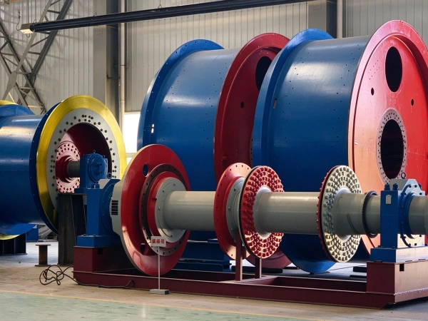
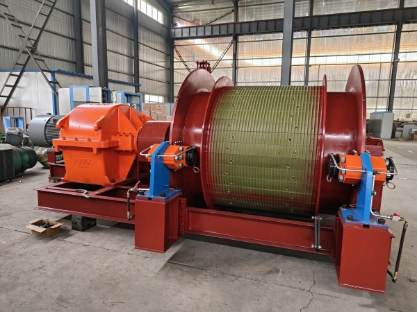
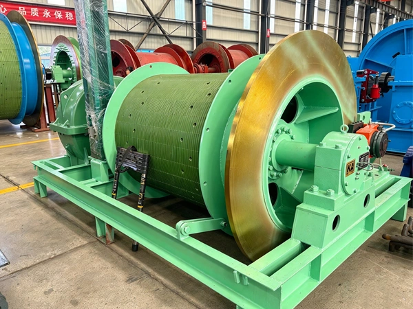
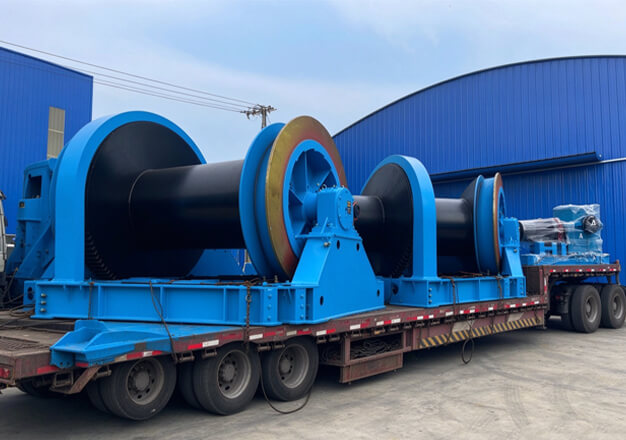
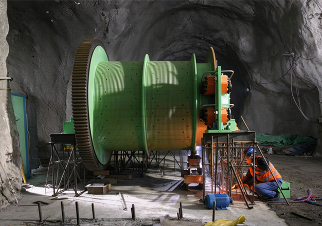
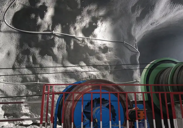
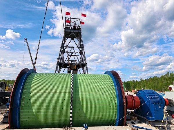
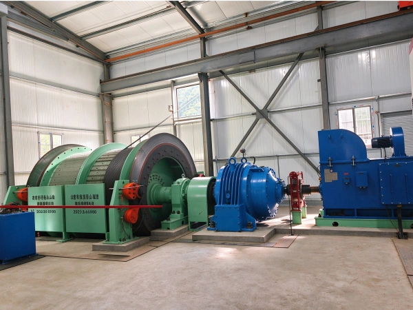
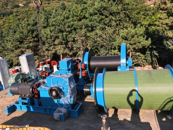
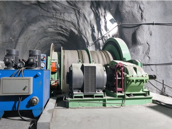
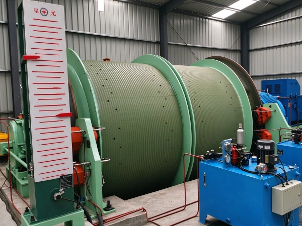
The 2JTP mining winch is a double-pulley lifting device specifically designed for mining applications. It is primarily used in inclined galleries or small vertical shafts in coal mines, metal mines, and non-metallic mines, and is suitable for lifting coal, ore, and gangue, as well as for transporting personnel and materials and equipment. Structural components: main shaft assembly, disc brake, reducer, coupling, motor, hydraulic station, depth indicator, working braking mechanism, and electrical control system.
Core structural composition:
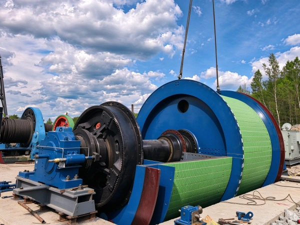
- Main spindle assembly: comprising the main spindle, fixed drum, movable drum, brake disc, rope-adjustment clutch, hub, bearing housing, bearing, and plastic liner
- Reduction gearboxes: hard-face reduction gearboxes and soft-face reduction gearboxes
- Motor: Three-phase asynchronous variable-frequency motor
- Braking system: includes disc brakes and a hydraulic unit
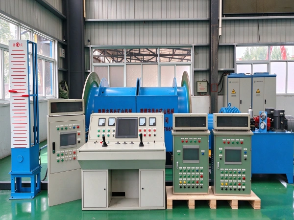
- Depth indicator: arch-type
- Couplings: bevel gear couplings and elastic pin couplings
- Operating braking mechanism: electric hydraulic brake
- Electrical control system: includes power frequency converter cabinet, braking cabinet, and control console
Core Structure and Design Features
It employs a split-beam drum configuration (facilitating transport and installation); the housing is made of high-strength low-alloy steel Q345A, and the surface features helical rope grooves formed by pressing to reduce wear on the steel wire rope;
Both ends of the spindle are equipped with adjustable double-row roller bearings, enabling full rolling transmission and achieving an overall efficiency of ≥90%.
Rear disc brakes with butterfly springs provide braking force; the hydraulic unit is driven with a response time of <0.3 seconds, supporting secondary braking and electro-hydraulic proportional adjustment;
Equipped with a manual gear-type rope-adjustment clutch, it supports rapid engagement and precise rope adjustment.
Planetary gear reducers or split-center drive reducers provide smooth transmission and low noise levels;
An optional PLC + variable-frequency speed control system is available, delivering energy savings of over 30%, supporting low-speed heavy-load startup, and reducing the impact on the power grid.
Application Scenarios and Limitations
Principle and Content
Parameter
| technical parameter | |||||||||||||||||
| model | drum | Maximum tensile force of the steel wire rope | Maximum tension differential of the steel wire rope | Maximum lifting height or transport length | wirerope | Average improvement rate | outline dimension(L × W × H) | Nominal weight of the main unit | |||||||||
| number | diameter | width | Center-to-center distance between the two rollers | manned | Load | manned | Load | One layer of wrapping | Two-layer winding | Three-layer winding | Maximum diameter | Total fracture strength | |||||
| unit | m | kN | m | mm | Kn | m/s | mm | Kg | |||||||||
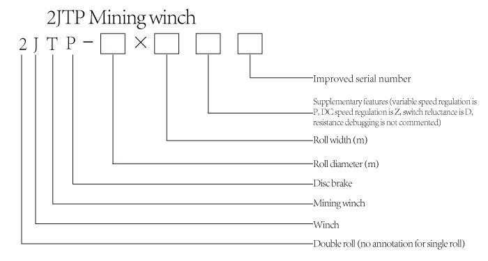
| parameter | 2JTP-1.2×0.8 | 2 | 1.2 | 0.8 | 0.87 | 15 | 21 | 15 | 20 | 171 | 344 | 536 | 14 | 137 | 2 | 5527×3000×1800 | 11915 |
| 2JTP-1.2×1 | 2 | 1.2 | 1 | 1.07 | 15 | 21 | 15 | 20 | 218 | 439 | 680 | 14 | 137 | 2 | 5815×3000×1800 | 13134 | |
| 2JTP-1.6×0.9 | 2 | 1.6 | 0.9 | 0.97 | 31 | 42 | 30 | 30 | 182 | 367 | 576 | 20 | 279 | 2.58 | 6203×3000×2000 | 18800 | |
| 2JTP-1.6×1.2 | 2 | 1.6 | 1.2 | 1.27 | 31 | 42 | 30 | 30 | 251 | 505 | 786 | 20 | 279 | 2.58 | 6860×300×2200 | 20936 | |