Overview
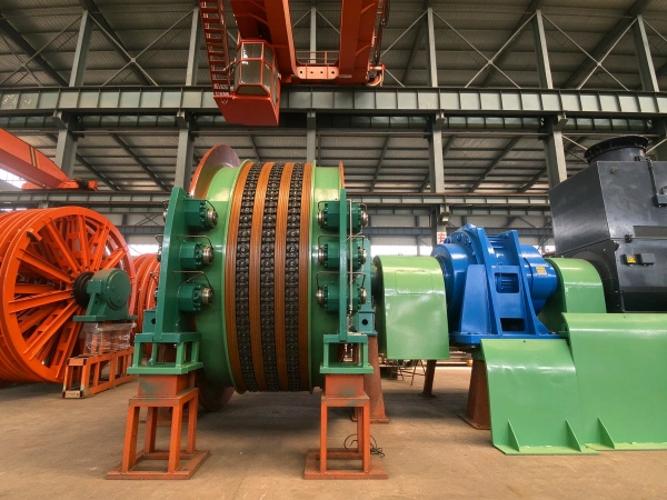
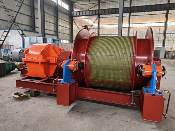
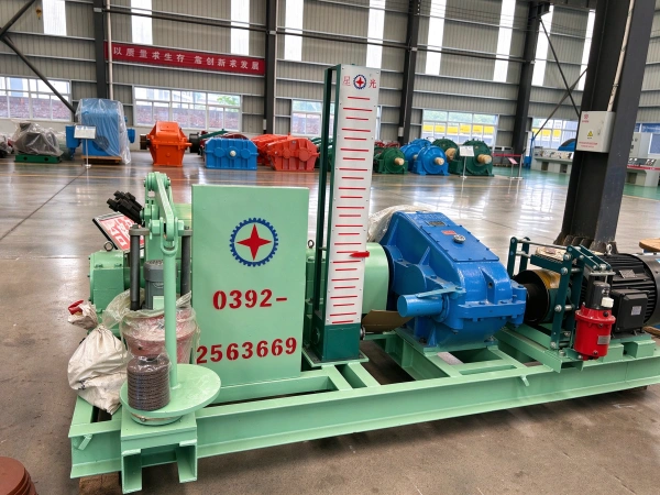
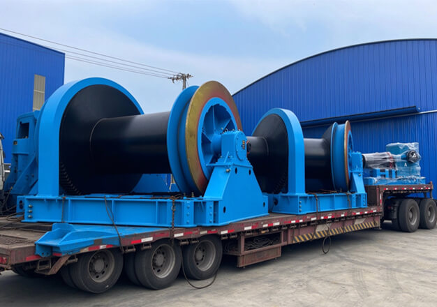
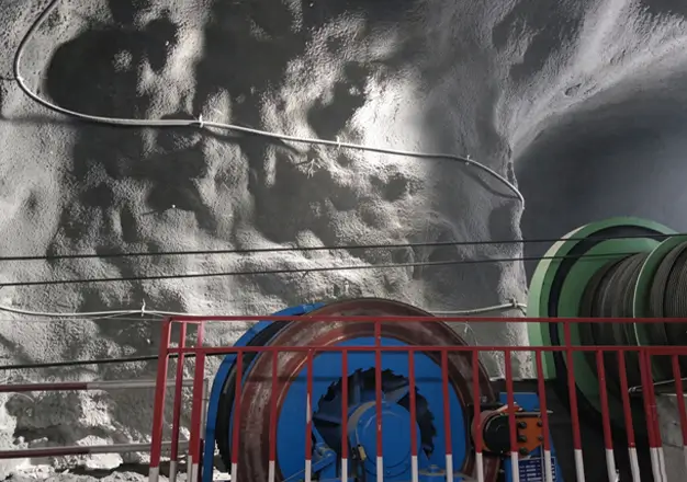
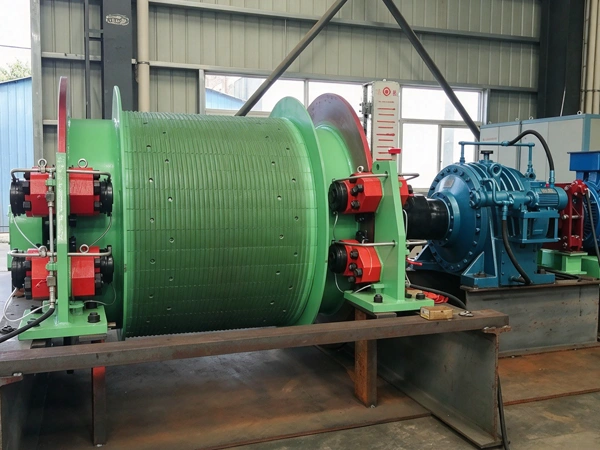
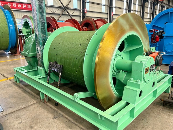
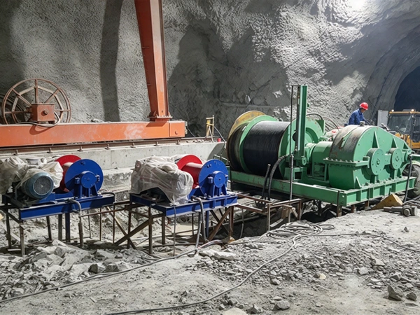
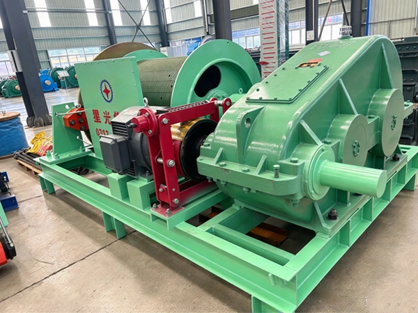
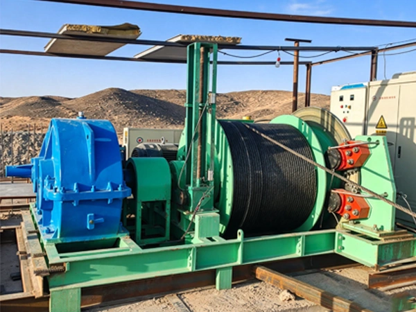
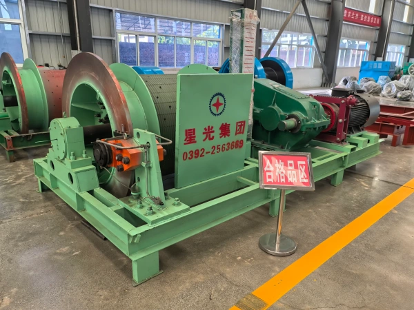
The JTP mining winch is lifting equipment specifically designed for mining applications. It is primarily used in inclined galleries or small vertical shafts in coal mines, metal mines, and non-metallic mines, and is suitable for lifting coal ash, ore, and gangue, as well as for transporting personnel and materials and equipment. Structural components: main shaft assembly, disc brake, reducer, coupling, motor, hydraulic station, depth indicator, working braking mechanism, and electrical control system.
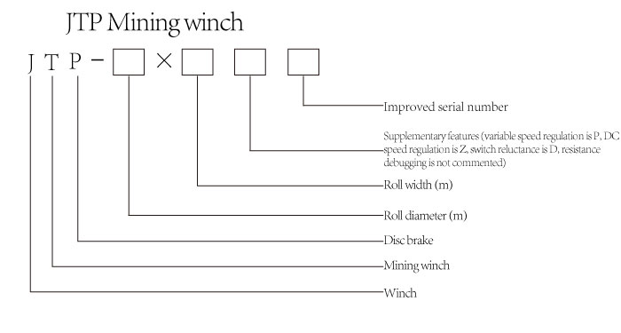
Features
Core structure and design features: multi-layered safety protection system, high-strength durable construction, precise and flexible speed regulation, compact and efficient design, and a wide range of models and specifications
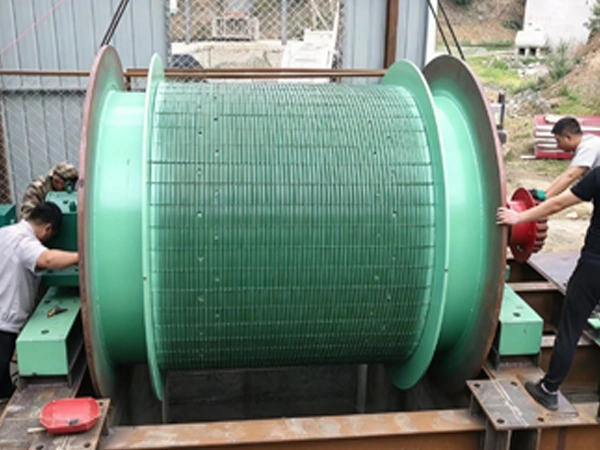
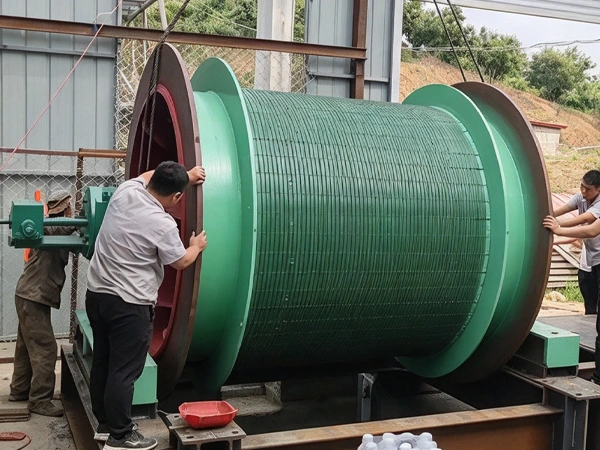
The coil adopts a split-type or integral-type design (for underground transportation and installation), is fabricated from Q345A high-strength steel, and has spiral rope grooves pressed into its surface to reduce wear on the steel wire rope;
Both ends of the spindle are equipped with adjustable double-row roller bearings; the transmission efficiency is ≥90%, and the design supports flat high-torque frictional coupling.
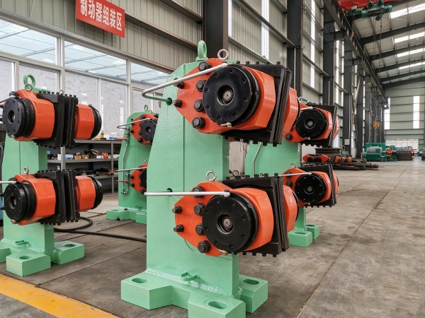
Disc brake: rear-mounted cylinder design; braking force is provided by disc springs and driven by a hydraulic unit (response time <0.3 seconds); braking torque ≥ 3 times the maximum static torque;
Supports secondary braking and electro-hydraulic proportional regulation; a safety brake is automatically engaged when power is disconnected.
Reduction gearboxes: planetary or cylindrical gear reduction gearboxes featuring tooth surface hardening (material 20CrMnTi, carburized and quenched), providing smooth transmission and low noise;
Speed control system: supports resistive speed control, variable-frequency speed control (with energy savings exceeding 30%), or DC speed control; it is also compatible with PLC control for remote monitoring and fault diagnosis.
Security Protection Features
Application Scenarios and Limitations
Structural Composition
- Main shaft assembly: comprising the main shaft, drum, brake disc, hub, bearing housing, bearing, and plastic liner
- Reduction gearboxes: hard-face reduction gearboxes and soft-face reduction gearboxes
- Motor: Three-phase asynchronous variable-frequency motor
- Braking system: includes disc brakes and a hydraulic unit
- Depth indicator: arch-type
- Couplings: bevel gear couplings and elastic pin couplings
- Operating braking mechanism: electric hydraulic brake
- Electrical control system: includes power frequency converter cabinet, braking cabinet, and control console
Principle and Content
Start the main motor → transmit power to the high-speed shaft of the reducer via an elastic coupling → reduce speed through a two-stage gear reduction → transmit power from the reducer’s driven shaft to the main shaft assembly via a gear coupling.
By reversing the motor’s direction of rotation, the drum winds or unwinds the steel wire rope, thereby driving the lifting container to move back and forth up and down within the wellbore.
Normal operation: the hydraulic station supplies pressure, and the disc brake releases its brake.
During braking: the hydraulic unit releases pressure, causing the disc brake to clamp the brake disc.
Safety protection: When an abnormal condition occurs (e.g., over-winding or overspeed), the protection device is triggered and immediate braking is initiated.
Motor rotation → speed reduction and torque increase → drum rotation → wire rope winding/unwinding → container lifting and lowering
Parameter
| technical parameter | ||||||||||||||||
| model | drum | Maximum tensile force of the steel wire rope | Maximum tension differential of the steel wire rope | Maximum lifting height or transport length | wirerope | Average improvement rate | outline dimension(L × W × H) | Nominal weight of the main unit | ||||||||
| number | diameter | width | manned | Load | manned | Load | One layer of wrapping | Two-layer winding | Three-layer winding | Maximum diameter | Total fracture strength | |||||
| unit | m | kN | m | mm | kN | m/s | mm | Kg | ||||||||
| parameter | JTP-1.2×1.0 | 1 | 1.2 | 1 | 15 | 21 | 15 | 21 | 218 | 440 | 681 | 14 | 137 | 2 | 3867×3000×1800 | 9675 |
| JTP-1.2×1.2 | 1 | 1.2 | 1.2 | 15 | 21 | 15 | 21 | 230 | 500 | 790 | 14 | 137 | 2 | 4689×300×1800 | 10800 | |
| JTP-1.6×1.2 | 1 | 1.6 | 1.2 | 31 | 42 | 31 | 42 | 251 | 506 | 786 | 20 | 279 | 2.58 | 5692×3000×2200 | 12910 | |
| JTP-1.6×1.5 | 1 | 1.6 | 1.5 | 31 | 42 | 31 | 42 | 290 | 610 | 970 | 20 | 279 | 2.58 | 6023×3000×2200 | 15860 | |