Overview
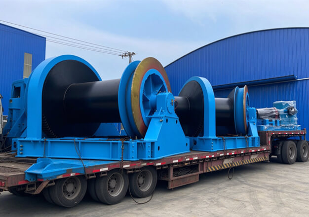
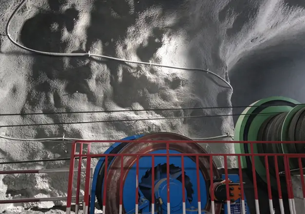
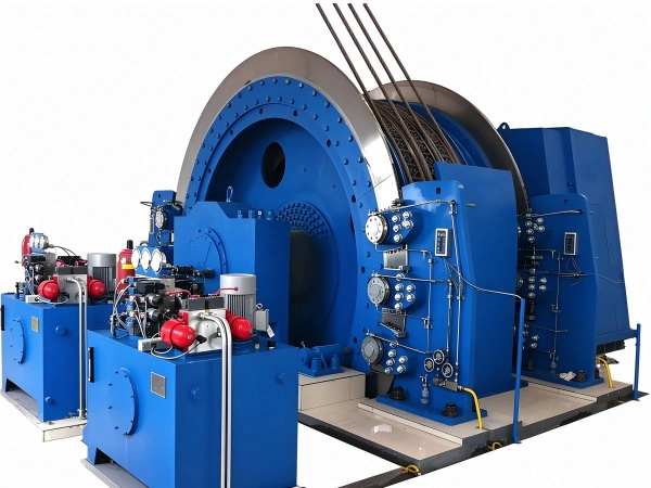
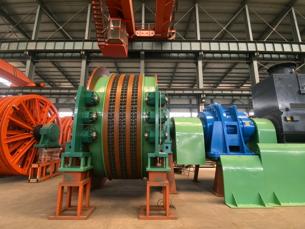
The JKMD multi-rope friction hoist series is designed and manufactured in accordance with standards including Q/YX007-2021 “Multi-rope Friction Hoists,” AQ1036-2007 “Safety Inspection Code for Multi-rope Friction Hoists for Coal Mines,” and GB/T10599-2010 “Multi-rope Friction Hoists.” These hoists are primarily used in deep shafts (lifting height ≥ 600 m) or ultra-deep shafts in coal mines, metal mines, and non-metallic mineral mines, where they are employed for personnel hoisting, material transport, and the lowering of large equipment. The equipment adopts a ground-mounted layout combined with multi-rope friction transmission technology; the main pulleys are installed on concrete foundations, and the system can accommodate 4–8 steel wires. It features high installed capacity, low infrastructure costs, and strong operational stability, making it a core piece of equipment for efficient transport in deep-shaft mines.
Core Advantage
Based on the principle of multi-rope friction drive, the lifting container is raised and lowered by the frictional force between the steel wire rope and the friction pad. This system features a relatively small steel wire rope diameter, a compact friction wheel, high lifting capacity, and a high safety rating.
Suitable for deep-well extraction operations with an annual production capacity exceeding 1.2 million tonnes and a well depth not exceeding 2,100 meters.
Operational Principle
The KMD mine hoist uses a variable-frequency motor as its power source and implements ultra-deep-well hoisting operations through a closed-loop process comprising “ground-mounted friction drive–counterweight tension balance–variable-frequency speed control–triple safety braking”; the specific operating principle is as follows:
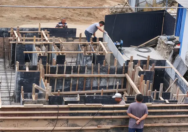
A variable-frequency motor drives a planetary reducer via a coupling; the output shaft of the reducer drives the drive wheel to rotate, which, through the friction between a high-friction coefficient pad mounted on the drive wheel and multiple steel wire ropes, pulls the wire ropes into motion. The drive wheel is mounted on the ground using a large radial roller bearing and installed on a concrete foundation, with a load-bearing capacity exceeding 5000 kN, thereby ensuring stability under deep-well, heavy-load operating conditions;
The system is equipped with a hydraulic tension balancing device; a tension cylinder is connected to the top end of each steel wire rope, and the tension in each individual rope is monitored in real time via a pressure sensor. When the tension differential exceeds 5%, the control system automatically adjusts the cylinder pressure to ensure uniform tension across all steel wire ropes; additionally, a tail-rope suspension device is installed to balance the tension differential generated by the self-weight of the steel wire ropes during the hoisting process.
The hoist is equipped with a disc brake assembly whose braking torque is no less than three times the maximum static braking torque; the disc brakes are engaged through hydraulic and electrical control. The hoist employs a combined mechanical, electrical, and hydraulic system composed of various sensors and control components for overall machine monitoring and protection;
A high-precision shaft encoder (resolution ≤ 0.1°) provides real-time data on the main drive wheel speed; the PLC system calculates the container’s position and velocity, which, together with a beam-type depth indicator, enables dual-position monitoring. When the container approaches the wellhead or the well bottom, deceleration control is automatically triggered, achieving a stopping accuracy of ±30 mm.
Nuclear Structure
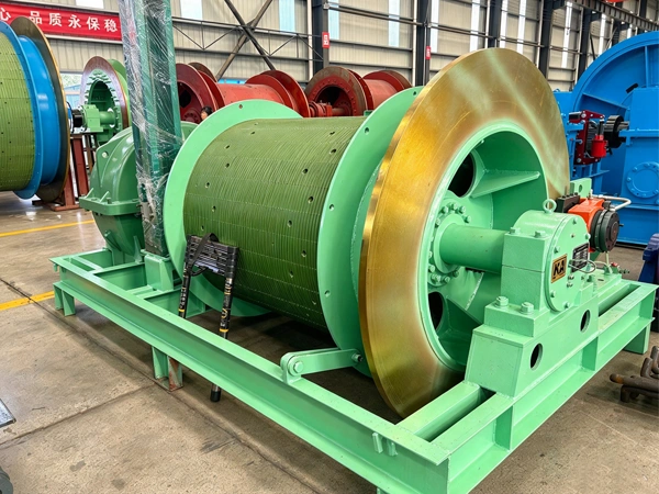
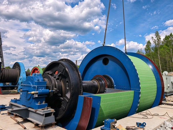
The friction wheels employ a single or double brake disc design; the well-tower configuration is equipped with a single rope groove, whereas the ground-mounted configuration is equipped with dual rope grooves and a rope adjustment device;
The lining material is made of PVC or phenolic resin, ensuring a high coefficient of friction and excellent wear resistance.
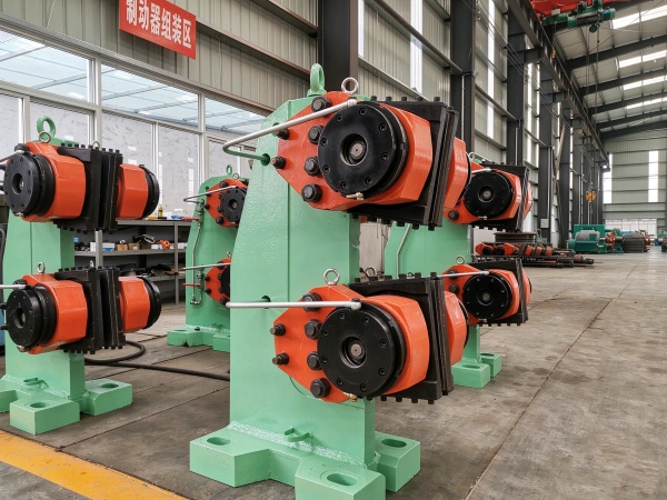
Equipped with a rear-mounted disc brake (with a hydraulic cylinder) and supporting electro-hydraulic integrated control; the braking torque shall be no less than three times the maximum static braking torque;
Hydraulic stations are available in two types: medium-low pressure (constant braking delay) and medium-high pressure (constant deceleration/constant braking torque), and are equipped with pressure sensors and transmitters.
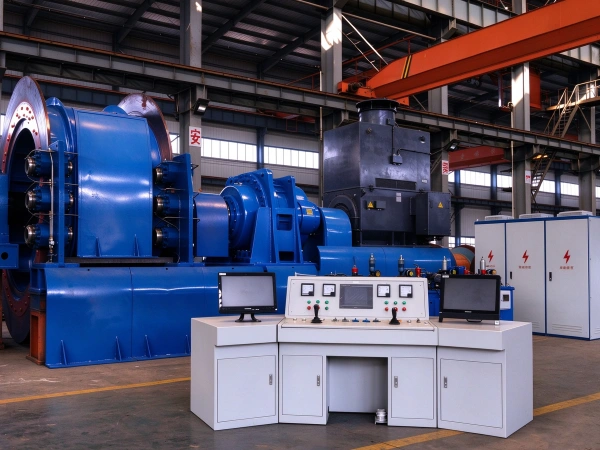
The spindle is directly driven by a low-speed motor (without a speed reducer) or driven via a planetary gear reducer, with a transmission efficiency of ≥90%;
DC motors or AC variable-frequency motors are available as optional equipment; the power range spans 22 kW to 11,600 kW, and multi-motor parallel drive is supported.
The control console integrates a digital depth indicator, an industrial video monitoring interface, and a PLC control module, supporting manual, semi-automatic, and fully automatic operating modes;
Equipped with the ASCS-3 fully digital speed regulation system, enabling precise speed control and fault diagnosis.
Security Protection Features
Application Scenarios and Limitations
Parameter
| technical parameter | ||||||||||||||
| model | Friction wheel diameter | Number of steel wire ropes | Maximum static tension difference of the steel wire rope | Maximum static tension of the steel wire rope | Maximum diameter of the steel wire rope | Wire rope spacing | Maximum acceleration | decelerator | Guide wheel diameter | Machine repositioning weight (excluding the motor) | Weight of the guide wheel displacement | Machine weight (excluding electrical equipment) | External dimensions (length × width × height) | |
| m | root | kN | kN | mm | mm | m/s | model | gear ratio | m | kg | kg | kg | m | |
| JKMD-2.25×4(I) | 2.25 | 4 | 65 | 215 | 22 | 250 | 10 | Xp800 | 73.510.511.5 | 2.25 | 6500 | 2300×2 | 46350 | 6.8×9.5×2.3 |
| JKMD-2.8×4(I) | 2.8 | 4 | 95 | 335 | 28 | 300 | 15 | Xp1000 | 2.8 | 11000 | 4100×2 | 63000 | 8.5×10×2.67 | |
| JKMD-3.25×4(I) | 3.25 | 4 | 180 | 520 | 36 | 300 | 15 | Xp1120 | 2.8 | 12700 | 4060×2 | 98008 | 8.9×9.5×3 | |
| JKMD-3.5×4(I) | 3.5 | 4 | 140 | 525 | 38 | 300 | 15 | Xp1120 | 3.5 | 17600 | 5500×2 | 101410 | 8.9×9.5×3 | |
| JKMD-3×4(III) | 3 | 4 | 140 | 450 | 32 | 300 | 16 | 3 | 11500 | 4540×2 | 74500 | 7×8.7×2.68 | ||
| JKMD-3.25×4(III) | 3.25 | 4 | 140 | 450 | 36 | 300 | 16 | 3.25 | 10940 | 5500×2 | 82192 | 7.2×8.9×2.98 | ||
| JKMD-3.5×4(III) | 3.5 | 4 | 220 | 590 | 38 | 300 | 16 | 3.5 | 10940 | 5500×2 | 84500 | 7.35×9.5×3 | ||