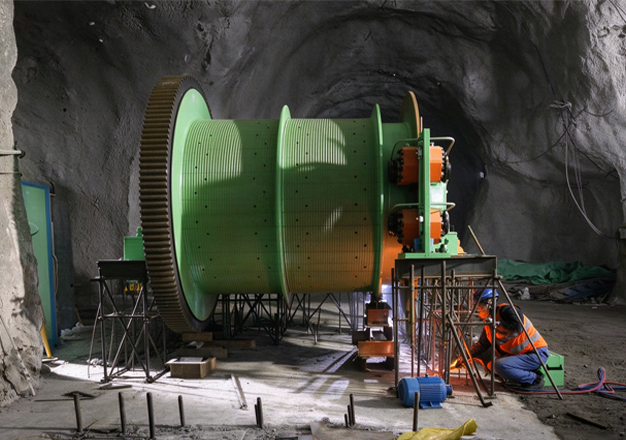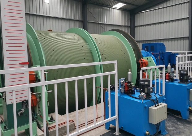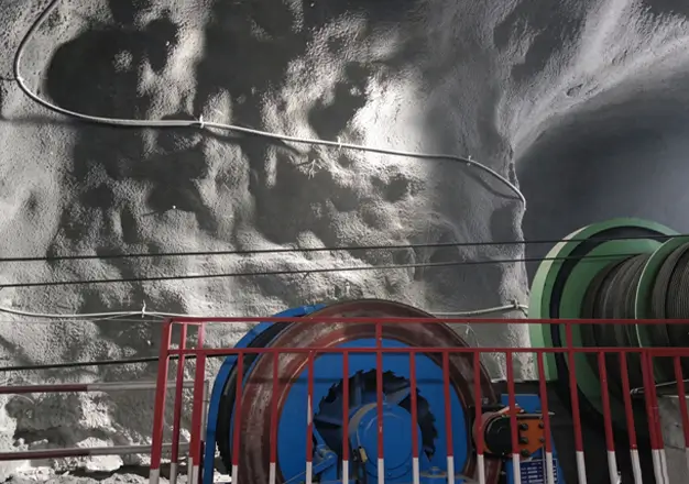
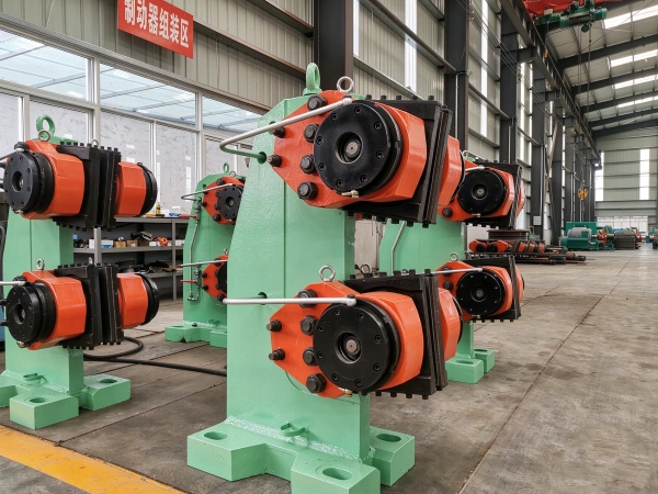
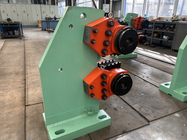
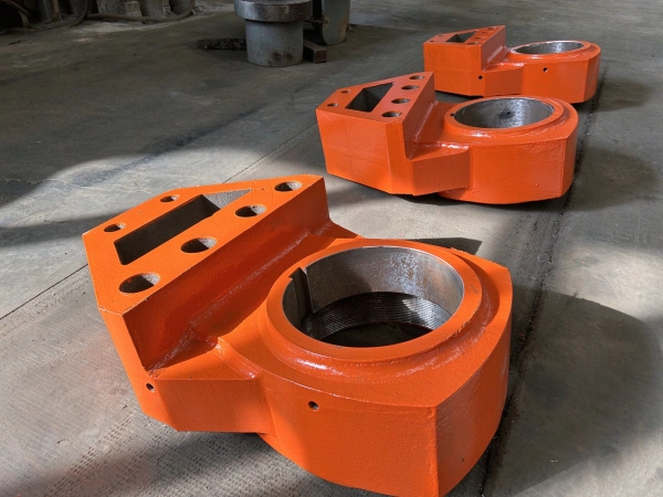
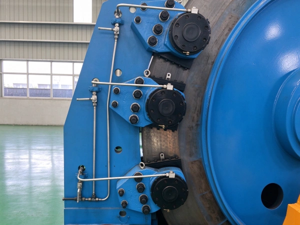
Overview
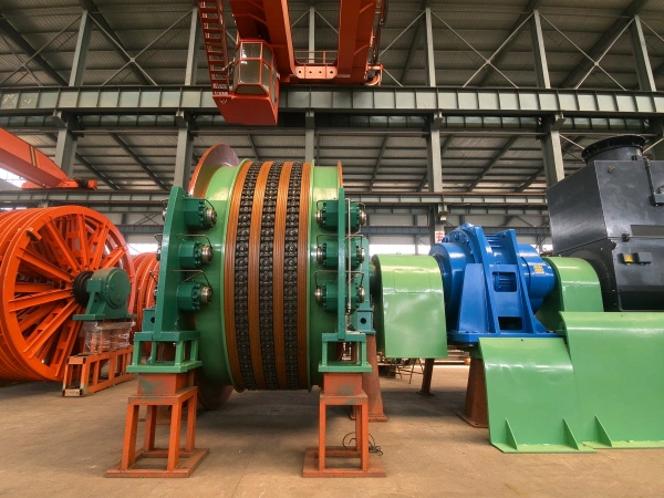
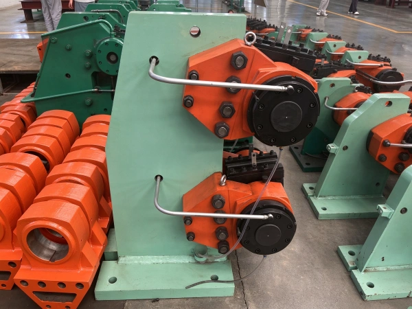
The rear-mounted dual-hydraulic-brake system based on ABB technology offers the advantages of low inertia, rapid response, excellent adjustability, high reliability, high versatility, a simple foundation, and convenient maintenance and adjustment.
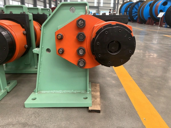
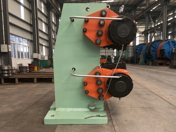
The novel disc brake assembly, together with the hydraulic station, constitutes the braking system of the mine hoist. The piping utilizes sleeve-type connectors to link the cylinders, pistons, and seals; the design has been optimized by drawing on foreign products (ABB); and the pistons employ low-temperature carbonitriding (QPQ) technology to enhance wear resistance and ensure zero leakage, thereby enabling both service braking and safety braking for the hoist. The disc brake is used for service braking and emergency braking on the mine hoist, with its drive and control provided by a separate hydraulic station. The disc brake features a symmetrical arrangement of dual brake discs, allowing service braking and safety braking to be implemented independently as required. During braking, the braking torque must not be less than three times the actual maximum static torque; the mechanical strength of all brake components must provide a sufficient safety factor to ensure safe and reliable operation under all operating conditions.
Disc brakes are hydraulically controlled and employ spring-based braking; they release the brake via hydraulic pressure, providing rapid response, safe and reliable braking, uniform distribution of braking force, excellent braking torque regulation, and high braking force transmission efficiency.
Structural Principle of Disc Brakes
A disc brake operates by using hydraulic oil to drive the brake shoes against the brake disc through a hydraulic cylinder, thereby generating friction and producing braking action. Disc brakes installed on high-speed shafts are available in two braking torque specifications: 10,000 N·m and 12,500 N·m; the brake disc diameter is 800 mm in both cases. Each set of brakes is equipped with four hydraulic cylinders, controlled by a single hydraulic system. Its key features include high braking torque, excellent heat dissipation performance, adjustable oil pressure, and the ability to vary the braking torque continuously during operation.
In hydraulic systems, an electromagnetic proportional relief valve has been selected for the design. This is an electro-hydraulic component that continuously and proportionally regulates the oil pressure in the hydraulic system in response to an input electrical signal. This series employs a manual electro-hydraulic controller installed on the operator’s console; the operator manually adjusts the potentiometer based on the indications of various instruments or through visual observation, thereby controlling the output current and, consequently, the oil pressure and braking torque, ensuring smooth and reliable conveyor startup and braking.
The operating principle of the disc brake is to release the brake by hydraulic pressure and apply braking force through spring force. As shown in Figure 1, when pressurized oil enters the front chamber of piston 7, it compresses the disc spring 14; this causes the adjustment screw 12 to drive the locking screw 11 and the plunger 10 to move rightward together with the piston, thereby driving the housing 3 and the brake shoe 1 to move rightward and releasing the brake. When the hydraulic pressure decreases, the disc spring causes the piston, adjustment screw, and plunger to push against the housing, causing the brake shoe to move leftward and thereby achieving braking.
Installation
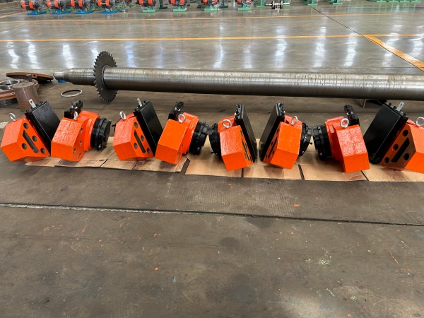
Before installation, clean all components of the disc-type gate and inspect the “O” -ring seal for any damage; replace it if damage is found. During assembly, do not strike the assembly with gravity, as this may cut the sealing ring. Then adjust the set screws so that the protrusion lengths of the two cylinders are equal.
Lift the disc-type gate body onto the flat surface of the foundation shims, then position and align the flat shims and inclined shims correctly, and install the anchor bolts, initially tightening them.
The centerline of the disc brake caliper should be aligned with the actual elevation of the spindle’s axis. As shown in the figure, first locate the axis horizontal line by extending it along both sides of the brake disc; then use a marking gauge to mark the intersection points between the brake disc, the friction circle, and the axis horizontal line; finally, draw a perpendicular from each intersection point to the axis horizontal line.
Merit
- Since the vast majority of the discs are exposed, their heat dissipation performance is very high, and they rarely cause a reduction in braking force. Consequently, even when applying reverse braking while traveling at high speed, stable braking performance can still be achieved.
- Unlike drum brakes, disc brakes exhibit almost no change in brake clearance even when the brake disc expands due to heat; instead, the clearance tends to decrease. Consequently, the brake pedal retains its clearance and is not affected by heat. Moreover, the pedal clearance can automatically adjust as the brake pads wear, thereby maintaining a constant value.
- Due to its simple structure, the brake tiles are easy to replace and service.
- In practice, there is no additional braking force; consequently, there is no phenomenon whereby the braking force increases as a result of such additional force. Because of this, no difference in braking performance between the left and right brakes occurs, and the vehicle is also less likely to be pulled toward one side when braking on only one side.
Parameter
| technical parameter | unit | model | ||||
| TP-40 | TP-63 | TP-80 | TP-100 | TP-25 | ||
| Maximum positive pressure | kN | 40 | 63 | 80 | 100 | 25 |
| Design friction coefficient | 0.4 | |||||
| Maximum operating oil pressure | MPa | 6.3 | 14 | 6.3 | ||
| Maximum specific pressure of brake shoes | N/cm | 53 | 84 | 95 | 116 | |
| Maximum allowable temperature of brake shoes | ℃ | ≤210 | ||||
| Piston effective area | Cm | 94 | 143.3/138 | 84.2 | 94.2 | 6.3 |
| weight | Kg | 140 | 200 | 140 | ||
| outline dimension | 490×380×297 | 90×380×297 | 515×420×296 | 15×420×296 | 490×380 | |
| Disc spring fatigue displacement | mm | 2 | 2.5 | 3 | 4 | |