Design Feature
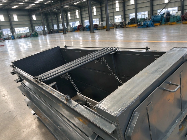
The suspension system serves as the connection mechanism between the cage and the wire rope; it constitutes a safety device. Most mines employ hydraulic helical suspension systems, hydraulic pad-type suspension systems, and multi-rope lifting systems with automatic tension balancing.
The multi-rope hoisting wire-rope tension automatic balancing suspension device is designed to address the inability of commonly used hydraulic screw-type and hydraulic pad-type rope adjusters—both domestically and internationally—to automatically adjust wire-rope tension. The device employs a sealed interconnected system combined with a pull-type clasp structure to achieve automatic balancing; it is characterized by safety, reliability, compactness, and aesthetic design. It enables high-precision automatic balancing of wire-rope tension under both dynamic and static conditions, thereby improving the operational safety, reliability, and efficiency of the hoist; reducing uneven wear of the pads and the frequency of wire-rope groove turning; extending the service life of both the pads and the wire rope; and significantly reducing maintenance workload.
Roller cage lugs are guiding devices installed on the cage that enable it to travel vertically along the rigid combined cage track. They serve both as guide wheels that direct the cage along the track and as connectors between the cage and the track, transmitting the forces acting between them. They are not only essential components ensuring the safe and stable operation of the cage but also critical elements that influence the operational stability of the wellbore equipment. Roller cage lugs act as the medium for interaction between the cage and the wellbore equipment; their performance plays a vital role in the operational quality of the wellbore’s rigid equipment. Therefore, the cage must be equipped with roller cage lugs that are suitable for the specific conditions of that cage and the cage track in the wellbore.
Roller materials are diverse, including wear-resistant rubber, ordinary rubber, and polymer materials. Buffering devices are even more varied, including conventional spring buffers, hydraulic buffers, torsional rubber-spring buffers, and disc springs. Among these, the liquid-immersed disc-spring roller bracket is considered the most ideal; its buffer spring has a composite structure that incorporates a spring, a spring preload, and a roller-position adjustment mechanism. The spring is a disc spring, and a sealing device is installed around the spring. The sealing housing also incorporates a spring preload adjustment mechanism and a spring suspension-length adjustment mechanism; the latter is used to adjust the roller position. The advantage is that the roller position can be easily and conveniently adjusted after wear occurs. The spring preload is easy to adjust, the spring is sealed within the housing, resulting in reliable operation and a long service life.
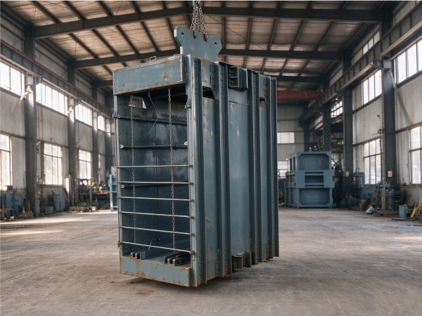
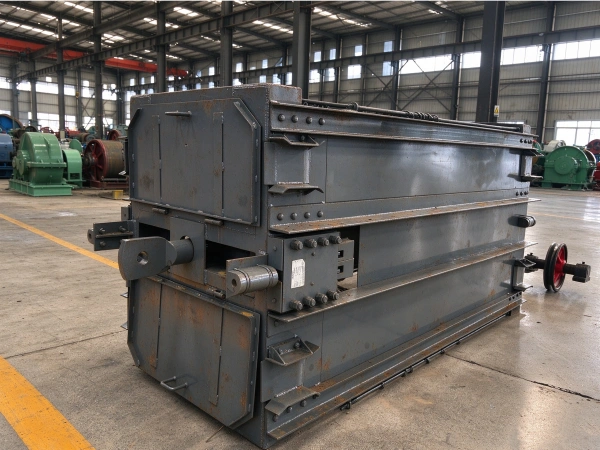
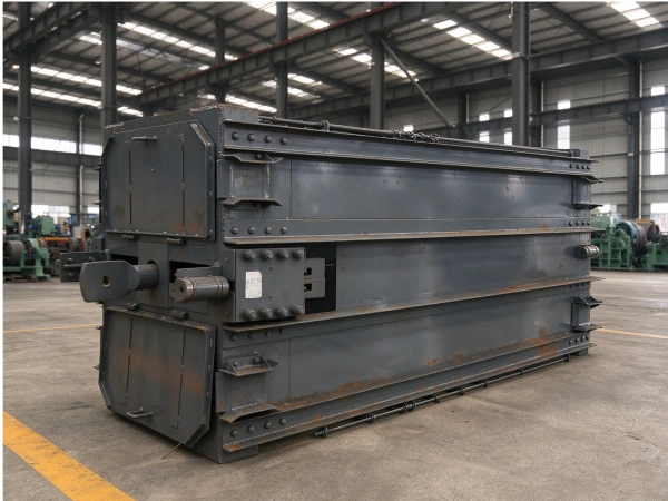
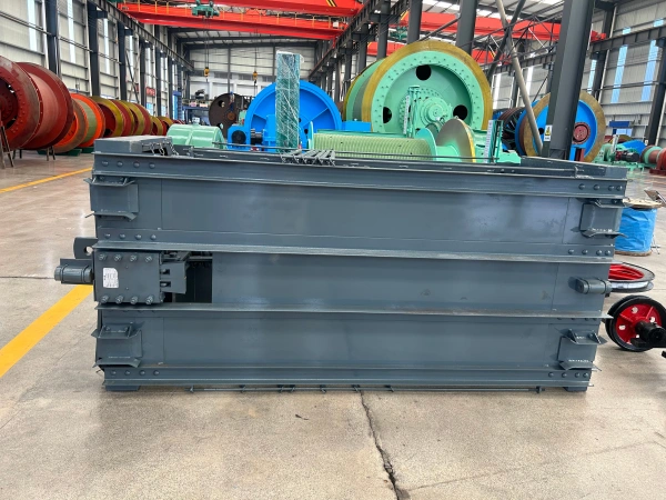
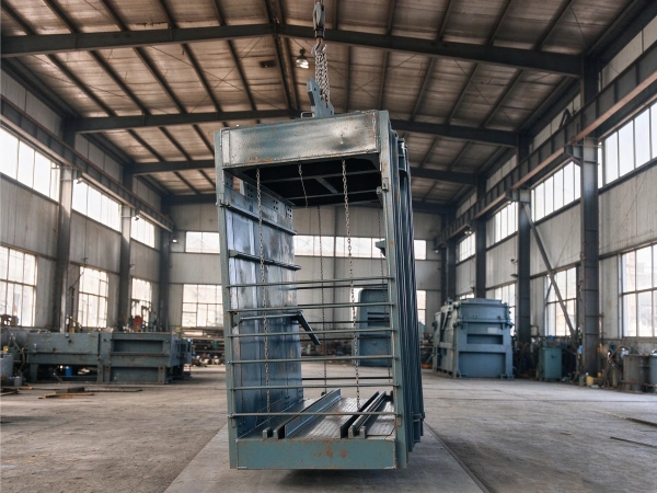
The main body consists of an upper, middle, and lower section, a cage restraint, and uprights. The suspension device is connected to the main body via a direct connection: the main and secondary lifting rods and the four-corner plates are eliminated, and the suspension device is directly attached to the main beam. This not only reduces the height of the cage and the height of the shaft tower but also significantly lightens the weight of the main body; the structure is simple and the installation is convenient.
The upper structure is the primary load-bearing component of the cage; it supports the full load of the cage, the self-weight of the equipment, the weight of the tail rope, and the frictional resistance between the rollers and the cage guide during operation. Consequently, the selection of materials and the requirements for manufacturing processes are extremely stringent. The main beam is also a primary load-bearing component of the cage; therefore, high attention must be paid to everything from material selection based on calculations to processing and fabrication. During manufacturing, it is essential to ensure that the rolling direction of the steel plate aligns with the direction of the applied load; a machining allowance of 10–20 mm should be reserved around the periphery; and nondestructive testing must be conducted in strict accordance with the relevant standards. Assembly and forming may proceed only after the components have passed these inspections.
The vehicle stopper employs rail surface protrusions for vehicle blocking and a sliding vehicle stopper; it is designed for use in conjunction with pin-tooth vehicle control equipment.
In summary, the design and manufacturing processes for large-capacity cage systems have been progressively refined, and these systems are widely used both domestically and internationally; consequently, they are the preferred equipment for large-scale mines.
Application
Cages are generally used for hoisting in mine auxiliary shafts to lift personnel, ore, equipment, materials, and other loads. In medium-and small-scale mines, cages may also be used for hoisting in the main shaft for coal transportation; thus, the cage is one of the key pieces of equipment in mine hoisting systems.
Classify
- Based on the number of hoisting steel wires, hoisting systems can be classified as single-wire cage systems and multi-wire cage systems. Single-wire cage systems are generally used in mines with depths not exceeding 400 m, whereas multi-wire cage systems are typically used in mines exceeding 350 m in depth.
- Based on the number of levels, cage structures can be classified as single-level, double-level, and multi-level cages.
- Based on the type of cage track, cages can be classified into those with wire rope tracks and those with rigid tracks; the latter can further be divided into rail tracks and composite steel tracks.
- Based on the model of the load car, the cage can be classified into 0.5 t, 1 t, 1.5 t, and 3 t load car cages.
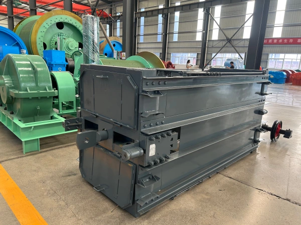
Both single-rope and multi-rope tank cages consist of two vertically arranged three-section side discs connected by cross beams. The primary structural configurations of tank bodies include the flat-steel truss type and the frame type, with the latter being more widely used. Tank-body joints are primarily connected by riveting, bolting, or welding.
Parameter
One of the technical features (single-rope series for coal mines)
| product name | model | Number of mine cars | Maximum rope diameter (mm) | permitNumber of passengers | pass in and outVehicle direction | weight(kg) |
| One ton of single-story single-cylinder tank cages | GLG(S)-1×1×1 | 1 | 31 | 12 | two-way | 3630 |
| One ton of double-walled bicycle containers | GLG(S)-1×2×1 | 1 | 35 | 12 | two-way | 4350 |
| One ton of single-story single-cylinder tank cages | GLG(S)-1×1×1 | 1 | 31 | 12 | two-way | 3160 |
| One ton of double-walled bicycle containers | GLG(S)-1×2×1 | 1 | 35 | 12 | two-way | 4438 |
| Three-ton single-story single-cylinder tank cage | GLG(S)-3×1×1 | 1 | 35 | 28 | two-way | 6534 |
| Three-ton double-deck single-cage tank car | GLG(S)-3×2×1 | 1 | 55 | 28 | two-way | 8541 |
| One ton of double-walled bicycle containers | GLG(S)-1×2×2 | 2 | 37 | 11 | – | 3428 |
| 1.5-ton double-deck single-cage container | GLG(S)-1.5×2×2 | 2 | 43 | 17 | one way | 5471 |
Technical Feature 2 (Multi-rope series for coal mines)
| Cage model | Number of mine cars | permitNumber of passengers | shell of tankconduct oneself with dignity | Maximum terminalload | Raise the first rope | – |
| diameter | quantity | – | ||||
| (vehicles) | (human being) | (kg) | KN | (mm) | root | |
| GDG-1/6/1/2 | 2 | 23 | 4656 | 157~279 | ?22~?32 | 4 |
| GDG-1/6/2/2 | 2 | 20 | 4281 | 158~267 | ?22~?32 | 4 |
| GDG-1/6/2/4 | 4 | 46 | 7959 | 282~381 | ?28~?32 | 4 |
Technical Feature 3 (Metallurgical Tank Cages)
(1) Single-rope cage:
| model | Number of layers | cross dimensions | Applicable mine vehicle model |
| 1# | 1st floor or 2nd floor | 1300×980 | YGC0.5、YFC0.5 |
| 2# | 1st floor or 2nd floor | 1800×1150 | YGC0.5、YGC0.7、YFC0.5 |
| 3# | 1st floor or 2nd floor | 2200×1350 | YGC1.2、YCC1.2、YFC0.5、YFC0.7 |
| 4# | 1st floor or 2nd floor | 3300×1450 | YGC2、YCC2、YFC0.5×2、YFC0.5×4 |
| 5# | 1st floor or 2nd floor | 4000×1450 | YFC0.7×2 |
(2) Multi-rope cage:
| model | Number of layers | cross dimensions | Applicable mine vehicle model |
| 1# | 1st floor or 2nd floor | 1300×980 | YGC0.5、YFC0.5 |
| 2# | 1st floor or 2nd floor | 1800×1150 | YGC0.5、YGC0.7、YFC0.5 |
| 3# | 1st floor or 2nd floor | 2200×1350 | YGC1.2、YCC1.2、YFC0.5、YFC0.7 |
| 4# | 1st floor or 2nd floor | 3300×1450 | YGC2、YCC2、YFC0.5×2、YFC0.5×4 |
| 5# | 1st floor or 2nd floor | 4000×1450 | YFC0.7×2、YGC1.2×2 |