Overview
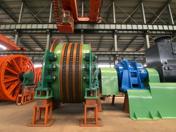
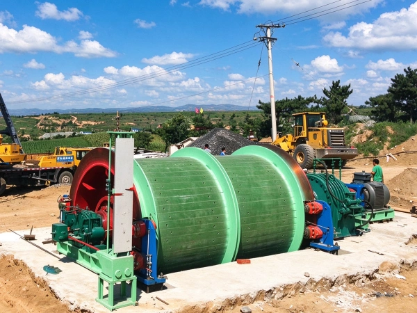
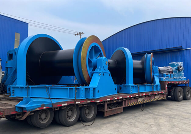
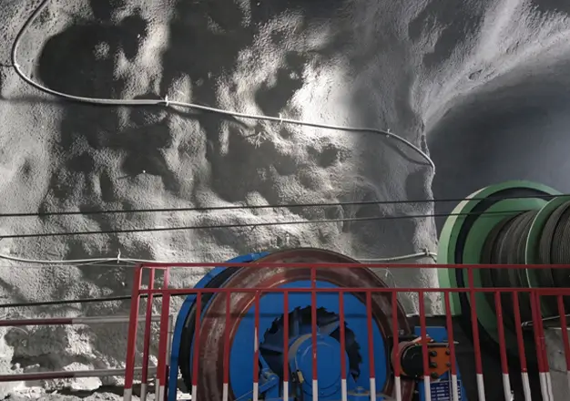
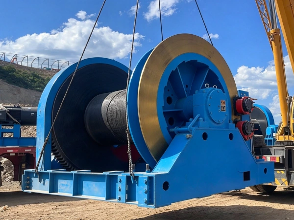
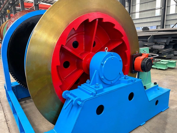
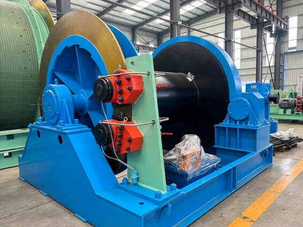
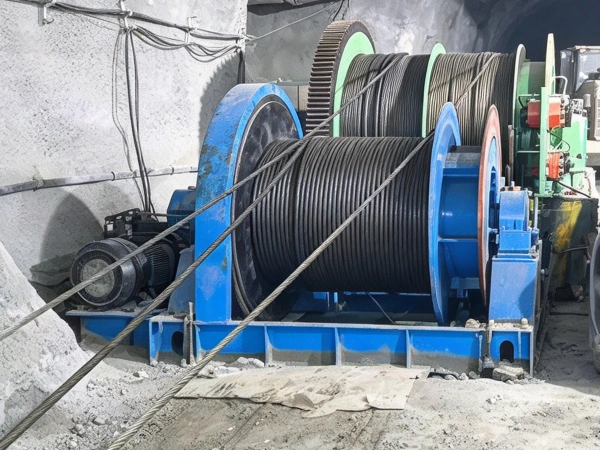
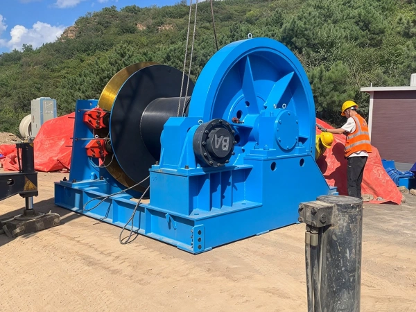
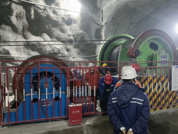
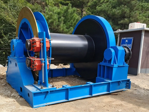
The JZ well-drilling winch is a specialized lifting device used in the excavation of vertical shafts in mining operations. It is primarily employed during the excavation of shafts for coal mines, metal mines, and non-metallic mines to suspend excavation equipment such as hoisting platforms, water pumps, water pipes, grouting pipes, and air ducts, while also serving to tension and stabilize the rope; its use as a means of transporting personnel is strictly prohibited. This product series strictly complies with the requirements of the “Well-Drilling Winch” standard (GB/T 15112-2017) and Articles 75 and 95 of the “Coal Mine Safety Regulations.” The winch adopts a single drum or a combination of multiple drums, with its core components comprising a main shaft assembly, a spherical worm gear reducer, a braking system, a motor, and an electrical control system.
Core Structure and Design Features
Main shaft assembly: The drum is connected to the gear and brake wheel via a copper sleeve and bolts. The main shaft rotates only with the drum and does not transmit torque. The wire rope is designed to emerge from the top.
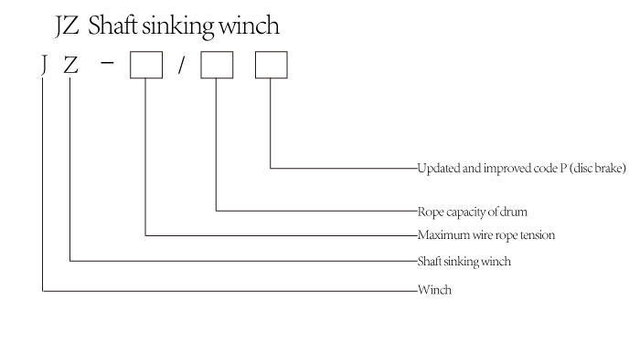
Manufactured from high-strength steel, it has a rope capacity of up to 1,800 meters (e.g., the JZ-40/1800 model).
It employs a “spherical worm gear pair + single-stage gear transmission” configuration; the handle switches between high and low speeds (high speed: 6 m/min; low speed: 3 m/min).
Double-spindle models (e.g., the 2JZ-16/1320 type) are equipped with a differential system that regulates the speed difference between the two spindles, thereby meeting the vertical positioning requirements of suspended equipment.
Operational braking: A brake shoe is employed; when the motor starts, the hydraulic push rod releases the brake; when the machine stops, braking is achieved by means of spring force.
Safety braking: employs a floating brake shoe design; a falling weight triggers power-off protection, ensuring reliable emergency braking.
Safety Protection and Lubrication
Application Scenarios and Limitations
Principle and Content
The well-drilling winch employs a winding mechanism. Its operating principle involves using an electric motor to drive a reducer, which rotates the drum and causes the steel wire rope to wind onto or unwind from the drum, thereby lifting or lowering a load. The specific operating procedure is as follows:
The motor transmits power to the reducer via an elastic coupling equipped with a brake wheel.
The reducer employs a spherical worm gear pair for speed reduction, supplemented by a single-stage variable-speed gear to convert high-speed, low-torque operation into low-speed, high-torque operation.
The reducer’s output shaft drives the spindle assembly via a gear transmission, causing the drum to rotate.
The wire rope is wound or unwound on a drum to lift or lower heavy loads.
Parameter
| technical parameter | ||||||||||
| model | Maximum static tensile force of the steel wire rope (kN) | Hydraulic system rated operating pressure (MPa) | Reduction gear ratio | Roller capacity rope (m) | Roll diameter (mm) | First-layer wire rope speed (m/s) | Wire rope diameter (mm) | Winch weight (t) | ||
| fast | low speed | fast | low speed | |||||||
| JZ-10/800P | 100 | 12 | 51 | 800 | 800 | 0.075 | 32 | 4.5 | ||
| JZ-10/1000P | 1000 | 5.5 | ||||||||
| JZ-16/1000P | 160 | 76 | 152 | 1000 | 1000 | 0.075 | 0.04 | 40 | 12 | |
| JZ-16/1300P | 1300 | 14 | ||||||||
| JZ-16/1500P | 1500 | 16 | ||||||||
| JZ-25/1300P | 250 | 76 | 152 | 1300 | 1050 | 52 | 15 | |||
| JZ-25/1500P | 1500 | 18 | ||||||||
| JZ-25/1800P | 1800 | 21 | ||||||||
| JZ-40/1500P | 400 | 76 | 152 | 1500 | 1250 | 60 | 24 | |||