Overview
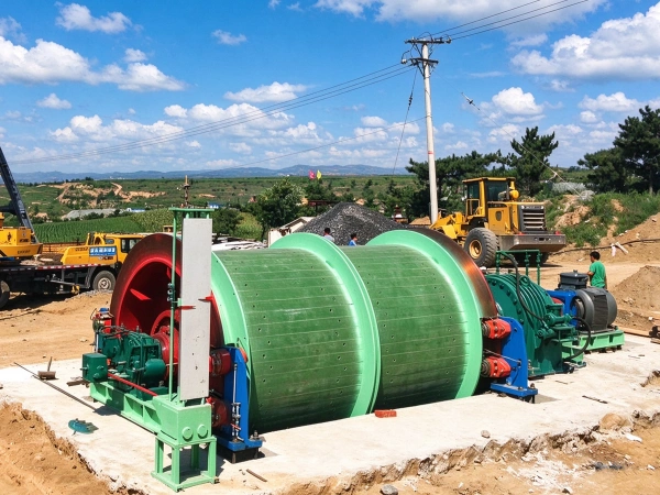
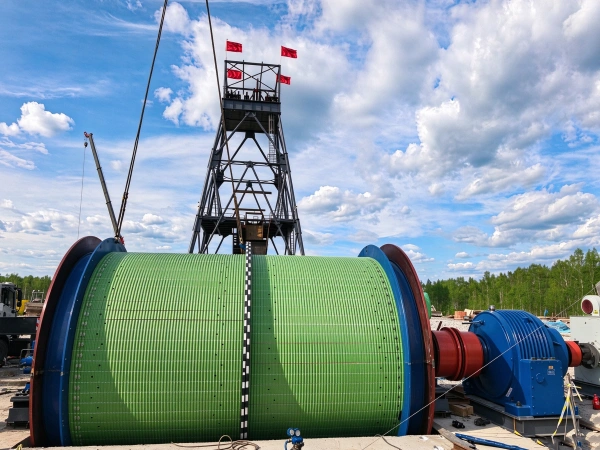
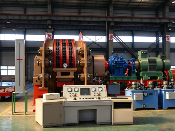
The JKM multi-rope friction-type hoist product series is designed and manufactured in accordance with standards including Q/YX007-2021 “Multi-rope Friction-type Hoists,” AQ1036-2007 “Safety Inspection Code for Multi-rope Friction-type Hoists for Coal Mines,” and GB/T10599-2010 “Multi-rope Friction-type Hoists.” These hoists are primarily used in deep shafts (lifting height≥600 m) or ultra-deep shafts in coal mines, metal mines, and non-metallic ore mines, where they are employed for personnel lifting, material transport, and the lowering of large equipment. The equipment operates on the principle of multi-rope friction transmission: the container is raised and lowered by the frictional force between the lead pulley and the steel wire rope. Typically, the system employs 4–8 steel wire ropes, providing a high lifting height, low single-rope tension, and high safety; consequently, it serves as the core equipment for efficient transport in deep-shaft mines.
Core Structure and Design Features
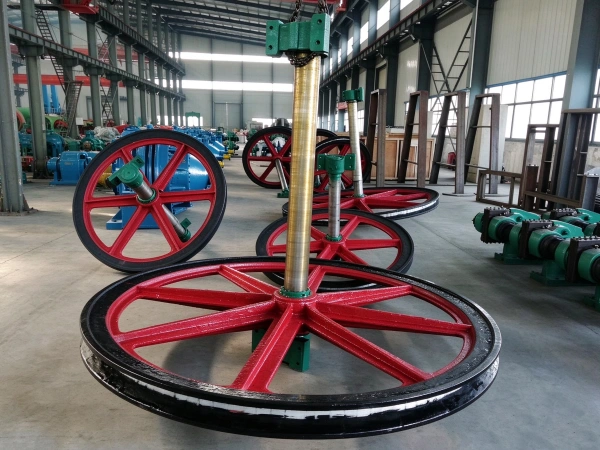
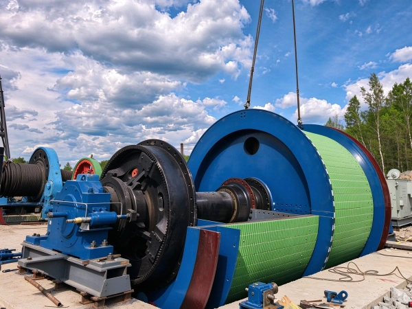
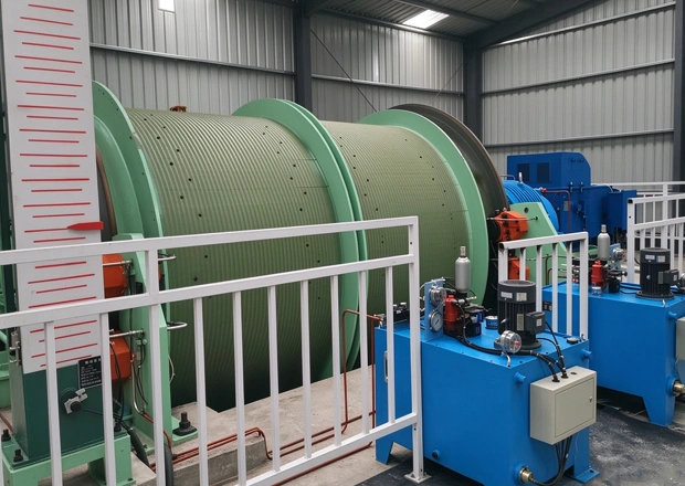
A fully welded friction wheel is employed, with a phenolic resin lining on its surface (friction coefficient ≥ 0.25); torque is transmitted through frictional coupling via a large flat surface;
The well tower design does not require a top pulley; the wire rope is directly wound around the friction pulley, thereby reducing the complexity of the equipment.
Disc brake: features a rear-mounted hydraulic cylinder configuration, with the disc spring providing the braking force; supports two-stage braking and constant-rate deceleration braking modes (response time <0.3 seconds), with braking torque ≥ 3 times the maximum static torque;
The hydraulic station supports electro-hydraulic proportional regulation and is equipped with pressure sensors to enable precise control.
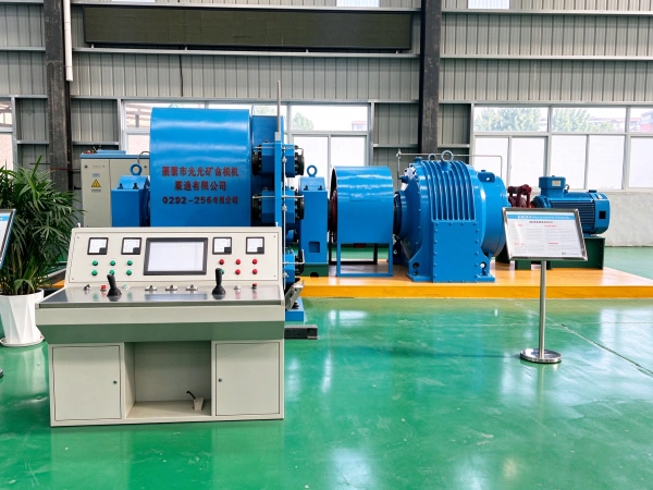
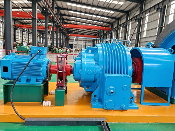
An optional planetary gear reducer (hardened tooth surface design, manufactured from 20CrMnTi material and subjected to carburizing and quenching) may be selected, or a direct-drive low-speed motor (without a reducer) may be used; transmission efficiency ≥ 90%;
Equipped with a permanent-magnet synchronous variable-frequency motor (with a maximum power of up to 8,000 kW), delivering energy savings of over 30%.
Integrates a PLC control system, supports manual, semi-automatic, and fully automatic operating modes, and is equipped with the ASCS-3 digital speed control system;
The depth indication system employs a dual-redundant design combining a mechanical pointer with a digital display, providing a positioning error of less than 0.5 meters.
Security Protection Features
Application Scenarios and Limitations
Operational Principle
The KM mine hoist uses a synchronous motor as its power source and implements deep-well hoisting operations through a closed-loop process comprising “friction drive—tension balance—variable-frequency speed control—safety braking”; the specific operating principle is as follows:
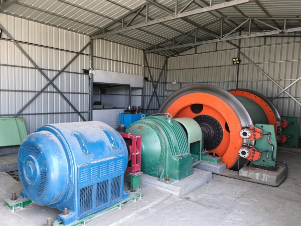
A variable-frequency motor drives a planetary reducer via a coupling; the output shaft of the reducer rotates the drive wheel, which, through the friction generated between the high-friction coefficient pad mounted on the drive wheel and multiple steel wire ropes, pulls the wire ropes into motion. The two ends of the wire ropes are connected to the lifting container and a counterweight, respectively, thereby enabling vertical lifting and lowering of the container.
The system is equipped with a hydraulic tension balancing device; a tension cylinder is connected to the top end of each steel wire rope, and the tension in each individual rope is monitored in real time via a pressure sensor. When the tension differential exceeds 5%, the control system automatically adjusts the cylinder pressure to ensure uniform tension across all steel wire ropes; additionally, a tail-rope suspension device is installed to balance the tension differential generated by the self-weight of the steel wire ropes during the hoisting process.nits;
Utilizing variable-frequency speed control technology and vector control, it enables continuous speed regulation from 0 to 100% of the rated speed; an S-shaped speed curve is employed during the start-up and braking phases to reduce impact loads; during the deceleration phase, energy recovery is achieved by feeding regenerative electricity back into the grid, resulting in significant energy savings;
The hoist is equipped with a disc brake assembly whose braking torque is no less than three times the maximum static braking torque; the disc brakes are engaged through hydraulic and electrical control. The hoist employs a combined mechanical, electrical, and hydraulic system composed of various sensors and control components for overall machine monitoring and protection;
A high-precision shaft encoder (resolution ≤ 0.1°) provides real-time data on the main drive wheel speed; the PLC system calculates the container’s position and velocity, which, together with a beam-type depth indicator, enables dual-position monitoring. When the container approaches the wellhead or the well bottom, deceleration control is automatically triggered, achieving a stopping accuracy of ±30 mm.
Parameter
| technical parameter | ||||||||||||||
| model | Friction wheel diameter | Number of steel wire ropes | Maximum static tension difference of the steel wire rope | Maximum static tension of the steel wire rope | Maximum diameter of the steel wire rope | Wire rope spacing | Maximum acceleration | decelerator | Guide wheel diameter | Machine repositioning weight (excluding the motor) | Weight of the guide wheel displacement | Machine weight (excluding electrical equipment) | External dimensions (length × width × height) | |
| m | root | kN | kN | mm | mm | m/s | model | gear ratio | m | kg | kg | kg | m | |
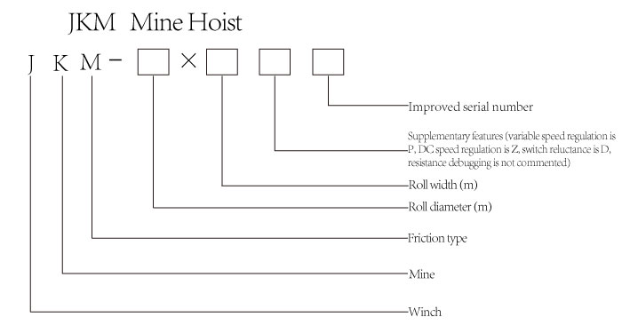
| JKM-2.25×4(I) | 2.25 | 4 | 80 | 230 | 24 | 200 | 10 | Xp800 | 73.510.511.5 | 2.25 | 6500 | 2100 | 33847 | 7.4×8×2.3 |
| JKM-2.8×4(I) | 2.8 | 4 | 140 | 340 | 28 | 250 | 15 | Xp1000 | 2.8 | 9820 | 2480 | 45300 | 8.5×10×2.65 | |
| JKM-2.8×6(I) | 2.8 | 6 | 180 | 510 | 28 | 250 | 15 | Xp1120 | 2.8 | 12700 | 3840 | 69000 | 8×8.5×2.68 | |
| JKM-3.25×4(I) | 3.25 | 4 | 180 | 520 | 36 | 300 | 15 | Xp1120 | 3.25 | 12700 | 3840 | 72000 | 8.9×8.9×2.98 | |
| JKM-3.5×4(I) | 3.5 | 4 | 220 | 590 | 38 | 300 | 15 | Xp1120 | 3.5 | 13500 | 4060 | 75000 | 9×9×3.2 | |
| JKM-3×4(III) | 3 | 4 | 140 | 450 | 32 | 300 | 15 | 3 | 8940 | 3060 | 45000 | 7×8.7×2.68 | ||
| JKM-3.25×4(III) | 3.25 | 4 | 112 | 480 | 32 | 300 | 15 | 3.25 | 10940 | 3060 | 48000 | 7.2×8.9×2.98 | ||
| JKM-3.5×4(III) | 3.5 | 4 | 220 | 525 | 35 | 300 | 15 | 3.5 | 13500 | 4060 | 56507 | 7.3×9×3.2 | ||
| JKM-3.5×6(III) | 3.5 | 6 | 220 | 820 | 35 | 300 | 15 | 3.5 | 18500 | 4760 | 74000 | 8×9×3.2 | ||