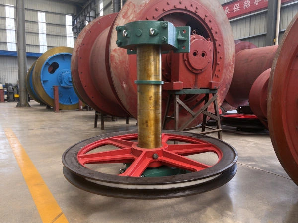
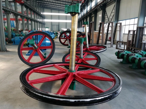
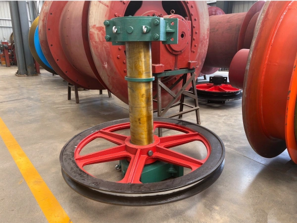
Overview
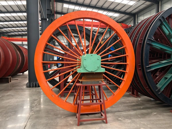
It offers low resistance and excellent wear resistance; its structure is relatively simple, making maintenance convenient. It is suitable for application scenarios that require compensation for the dynamic swaying of wire ropes, mitigation of impact vibration, and improvement of the stability and safety of lifting systems.
Application
Moving pulleys are widely used in mine hoisting systems and are particularly suitable for multi-rope friction hoists and applications requiring container guidance within the shaft. They are commonly employed in vertical or inclined hoisting and are used in conjunction with cages, bucket cars, or lifting buckets. Because they can automatically adjust the deflection angle of the wire rope, moving pulleys significantly enhance system stability and safety in mines with greater depths or longer hoisting distances. They are also suitable for certain temporary construction scenarios that require wire rope guidance in multiple directions, such as suspension systems during the shaft excavation phase.
Characteristic
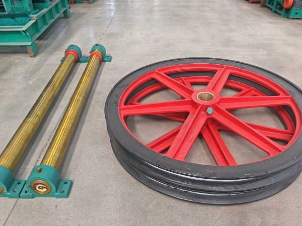
When the lifting container moves up and down within the wellbore, the wire rope comes into contact with the groove of the traveling pulley; frictional force drives the pulley body to rotate. Since the pulley body is mounted on a fixed shaft via rolling bearings, the rotational friction is extremely low, thereby efficiently converting the linear motion of the wire rope into the rotational motion of the pulley body and avoiding the energy losses and wear caused by sliding friction.
The wheel assembly typically employs rolling bearings, resulting in low rotational resistance; meanwhile, the axial sliding design also reduces the additional resistance caused by lateral tension in the wire rope, enabling the entire system to operate more smoothly.
Because the wire rope can consistently maintain proper alignment during operation, vibration and scraping are reduced, significantly improving the overall stability of the hoisting system and ensuring the safety and smooth operation of the lifting container while it moves within the cylinder.
Parameter
| technical parameter | |||||
| model | Bottom circular diameter of the rope groove, D | Rope groove radius R | Travel distance S | Applicable wire rope diameter | Allowable total breaking strength of steel wire ropes |
| mm | k | ||||
| TDG 600/9/300 | 600 | 9 | 300 | 14-16 | 160 |
| TDG 800/11/700 | 800 | 11 | 700 | >16-20 | 252 |
| TDG 1000/13.5/800 | 1000 | 13.5 | 800 | >20-24.5 | 382 |
| TDG 1400/16/740 | 1400 | 16 | 740 | >24.5-30 | 597 |
| TDG 1400/16/1350 | 1350 | ||||