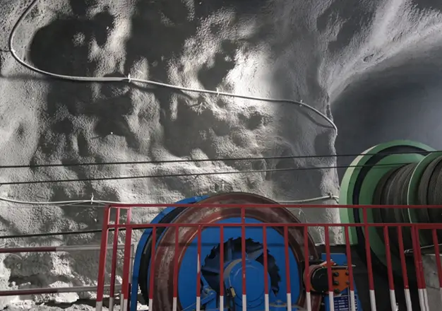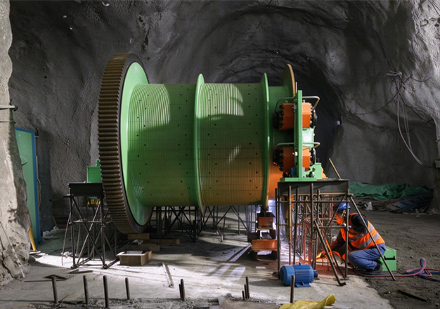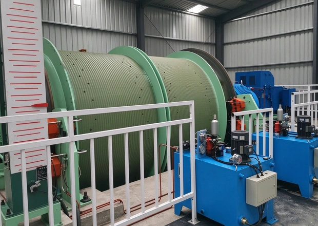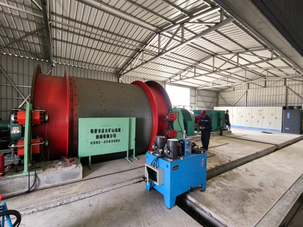
Overview
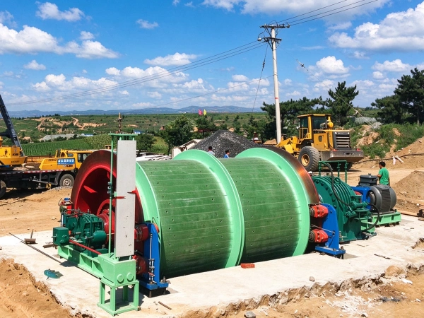
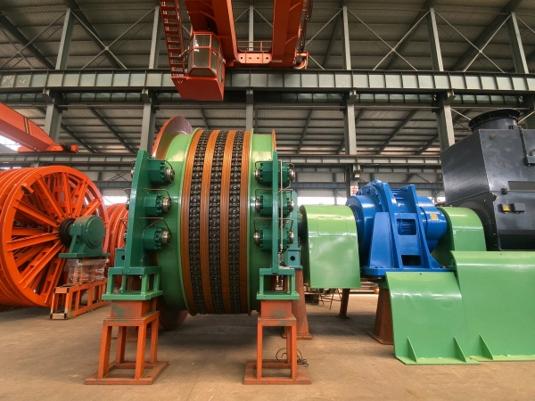
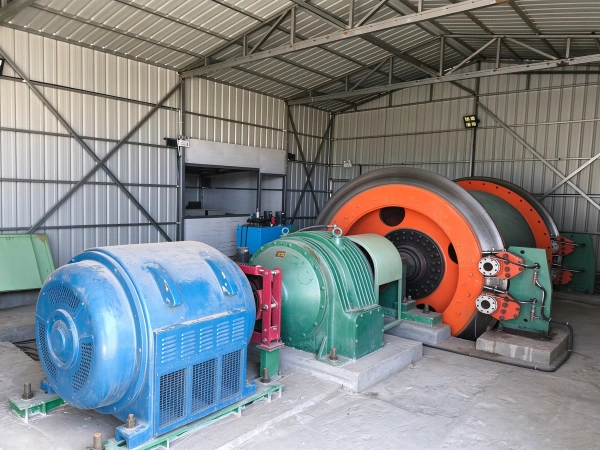
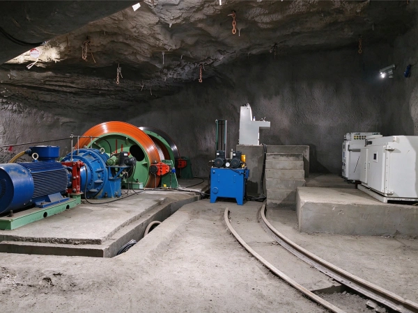
The JKB series explosion-proof and flameproof mine hoists are explosion-proof lifting equipment designed in accordance with the *Coal Mine Safety Regulations*, the GB/T 3836 series of explosion-proof standards, and GB/T 20961-2007, *Single-Rope Winding Mine Hoists*. They were specifically developed for high-gas and coal-dust explosion-risk environments in underground coal mines and are primarily used for personnel lifting, material transport, and equipment lowering in vertical and inclined shafts. The variable-frequency motor, hydraulic station, and electrical control system of this equipment are all designed with explosion-proof capabilities; the drum diameter ranges from 2 to 3.5 meters; and the single-rope winding configuration is suitable for operating conditions with a lifting height ≤ 1,200 m and a maximum static tension ≤ 150 kN. These hoists constitute the core transportation equipment for safe production in high-gas mines.
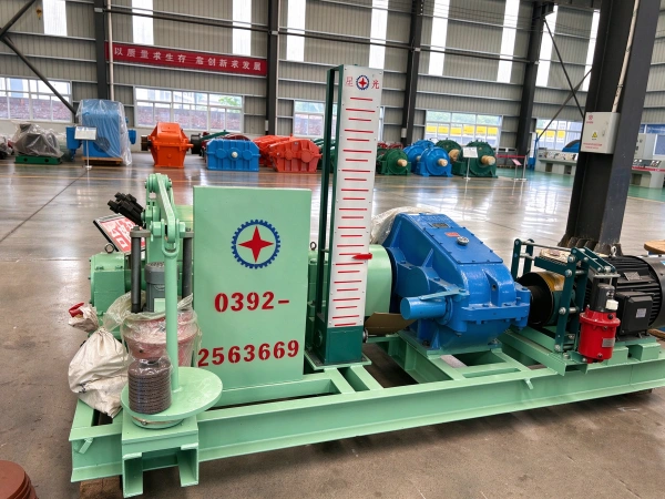
The JKB series hoists consist of an explosion-proof mechanical system and an intrinsically safe electrical control system: the mechanical core comprises the shaft assembly, planetary reducer, disc brake, explosion-proof motor, explosion-proof hydraulic unit, and explosion-proof depth indicator; the electrical control system incorporates an explosion-proof variable-frequency power cabinet, an explosion-proof PLC control cabinet, an explosion-proof reactor box, and an intrinsically safe operator console. All electrical components have obtained the mining-product safety certification mark (MA mark), ensuring safe operation in explosive environments with a methane concentration ≤ 1.0%.
Core Structure and Design Features
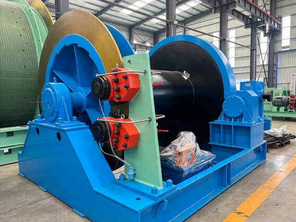
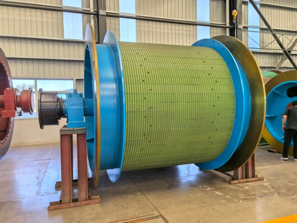
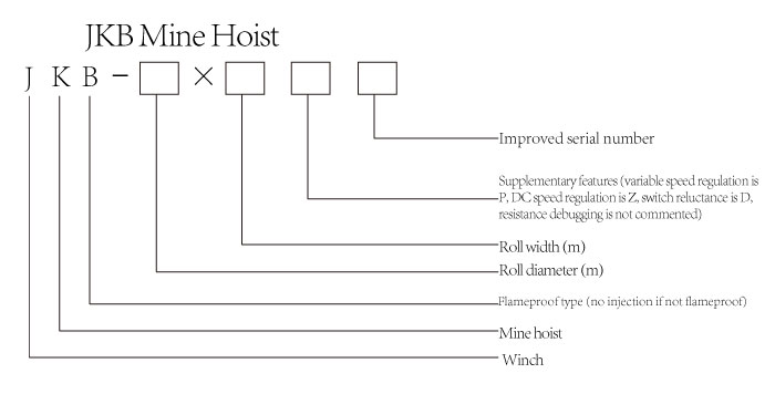
It employs a split drum configuration (e.g., JKB-2.5×2P), facilitating underground transportation and installation. The material is 16Mn high-strength steel, with a press-formed plastic rope groove on the surface to reduce wear.
The spindle and reducer are directly connected via a gear coupling, providing a transmission efficiency of ≥90%; the assembly is supported by double-row spherical roller bearings with high impact resistance.
Disc brake: Rear cylinder design; braking force is provided by disc springs; supports secondary braking and constant deceleration mode; braking torque is ≥3 times the maximum static torque.
Hydraulic power unit: rated operating oil pressure of 6.3 MPa; equipped with a proportional valve for pressure regulation, and supports automatic braking and redundant control during power failure.
Planetary gear reducer: tooth surface hardening design (material: 20CrMnTi, carburized and quenched); transmission ratio range: 20–31.5; low operating noise and long service life;
Variable-frequency motor: power range 200–800 kW; suitable for explosion-proof environments; energy savings exceed 30%.
Safety Protection and Explosion-Proof Characteristics
Application Scenarios and Limitations
Principle and Content
The JKB mine hoist uses an explosion-proof motor as its power source and performs lifting operations through an explosion-proof closed-loop process comprising “explosion-proof power transmission–explosion-proof braking control–intrinsically safe monitoring and interlocking”; the specific operating principle is as follows:
An explosion-proof motor (Ex d I Mb) transmits power to an explosion-proof reducer via an explosion-proof elastic coupling; after two-stage planetary gear reduction, the power drives the spindle assembly to rotate. The explosion-proof enclosures of all transmission components meet the dual requirements of “explosion resistance + explosion-proofing”; the clearance at the enclosure joints is ≤0.2 mm, ensuring that any internal explosion does not propagate to the external environment;
An explosion-proof disc brake is employed, with the braking force provided by a disc spring (single brake-pad pressure: 58 kN); the explosion-proof hydraulic unit controls brake release via an intrinsically safe solenoid valve; friction sparks generated during braking are contained within the explosion-proof chamber; the braking torque is set at three times the maximum static torque reserve; and the emergency braking deceleration is precisely controlled within the range of 1.5–1.6 m/s².
The explosion-proof variable-frequency cabinet employs vector control technology to achieve continuous speed regulation from 0–100% of the rated torque; the inverter output is suppressed for harmonic filtering by an intrinsically safe reactor, thereby preventing cable spark discharge; the speed regulation signal is transmitted via an intrinsically safe isolation barrier, ensuring that the energy in the control circuit is ≤1.2 W (the intrinsically safe limit) and preventing the generation of ignition sources;
The dual PLC intrinsically safe control system collects real-time signals from an explosion-proof shaft encoder (Ex d I Mb), a gas sensor (model KGJ16B), and a temperature sensor; when it detects a methane concentration ≥ 0.8% or a bearing temperature ≥ 75 °C, it immediately triggers the emergency braking of the explosion-proof brake, cuts off the power supply to the explosion-proof motor, and simultaneously issues an alert via an intrinsically safe audible and visual alarm;
All cables passing through the explosion-proof housing are equipped with explosion-proof sealed connectors (Ex d I); a dual labyrinth seal combined with an O-ring is installed between the main shaft and the explosion-proof housing to prevent gas from entering the explosion-proof chamber; the drum wooden liner is treated with flame-retardant impregnation, providing a stable coefficient of friction and preventing static electricity generation, thereby further enhancing explosion-proof safety.
Parameter
| technical parameter | |||||||||||||||||
| model | drum | Maximum tensile force of the steel wire rope | Maximum tension differential of the steel wire rope | Maximum lifting height or transport length | wirerope | Average improvement rate | outline dimension(L × W × H) | Nominal weight of the main unit | |||||||||
| number | diameter | width | Center-to-center distance between the two rollers | manned | Load | manned | Load | One layer of wrapping | Two-layer winding | Three-layer winding | Maximum diameter | Total fracture strength | |||||
| unit | m | kN | m | mm | kN | m/s | mm | Kg | |||||||||
| parameter | JKB-2×1.5P | 1 | 2.0 | 1.5 | / | 60 | 244 | 493 | 774 | 32 | 558 | 2.5 | 6664×3234×2600 | 27193 | |||
| JKB-2×1.8P | 1 | 2.0 | 1.8 | / | 60 | 299 | 604 | 942 | 32 | 558 | 2.5 | 7516×3234×2600 | 28230 | ||||
| JKB-2.5×2P | 1 | 2.5 | 2 | / | 90 | 329 | 665 | 1041 | 40 | 747 | 3 | 7575×3610×3300 | 38827 | ||||
| JKB-2.5×2.3P | 1 | 2.5 | 2.3 | / | 90 | 366 | 776 | 1210 | 40 | 747 | 3 | 8323×3610×3300 | 40585 | ||||
| JKB-3×2.2P | 1 | 3.0 | 2.2 | / | 130 | 358 | 765 | 1174 | 50 | 1215 | 3.7 | 9665×4550×2800 | 52914 | ||||
| JKB-3×2.5P | 1 | 3.0 | 2.5 | / | 130 | 414 | 878 | 1344 | 50 | 1215 | 3.7 | 9965×4550×2800 | 54134 | ||||
| JKB-3.5×2.5P | 1 | 3.5 | 2.5 | / | 170 | 483 | 1024 | / | 50 | 1530 | 4.3 | 10695×5020×3050 | 69612 | ||||
| JKB-3.5×2.8P | 1 | 3.5 | 2.8 | / | 170 | 549 | 1156 | / | 50 | 1530 | 4.3 | 10995×5020×3050 | 70558 | ||||